
So finally, the decoder works like a full subtractor. So the output is active low and the output can be obtained from NAND gate called difference function like high and borrow function also changes out to be high. These outputs can be connected to other NAND logic gates where the output changes to the borrow.įor example, if the input is 001, then the output will be 1 that means it is active. Now the outputs of the subtractor can be taken from 1, 2, 4 &7 to connect it to a NAND gate, then the output will be the difference. If the input of the subtractor is 000, then output ‘0’ will be active and if the input is 001, then the output ‘1’ will be active. The 3-8 decoders include three inputs as well as 8 outputs lik0 to 7 numbers. Based on the truth table, we can write the minterms for the outputs of difference & borrow.įor the different functions in the truth table, the minterms can be written as 1,2,4,7, and similarly, for the borrow, the minterms can be written as 1,2,3,7. The decoder includes three inputs in 3-8 decoders. Let’s assume decoder functioning by using the following logic diagram. The designing of a full subtractor using 3-8 decoders can be done using active low outputs. The truth table of full subtractor circuit using 4X1 multiplexer includes the following
4 bit adder subtractor circuit diagram code#
The verilog code for the full subtractor is shown below

For implementing this, we use the OR gate to combine the o/ps for the variable of Bout. First, we design a half subtractor then this module is used to implement a full subtractor. Now this instantiation can be used once we want to replicate an exact module or function for diverse input sets. For that, here we utilize instantiation of module. Lastly, we will unite these gate precise modules into an only module. In the following code, different modules can be defined for every gate. As in structural modeling, we explain various modules for every basic elemental arrangement. The logic diagram of this can be built using an AND gate, half subtractor circuits, and the combination of logic gates like AND, OR, NOT, XOR gates. Verilog Codeįor the coding part, first, we need to check the structural way of modeling of the logic circuit diagram.

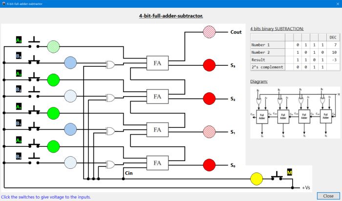
Actually, we can design the circuit so that output can be observed. The FA’s output is the Diff bit & if we invert the carry out then we can get the MSB otherwise Borrow bit. By adding this Minuend (noninverted input) & Subtrahend (Inverted Input), the LSB (carry input) of the FA circuit is 1, which means Logic High otherwise we subtract two binary digits using 2’s complement technique. Generally, invert the subtrahend inputs for the full adder using NOT gate otherwise an inverter. The conversion of the circuit from full adder to full subtractor can be done using 2’s complement technique. In such cases, a full adder cascaded circuit is used with the help of NOT logic gate. But if we want to subtract two otherwise more 1-bit numbers, this subtractor circuit is very helpful to cascade single bit numbers and also subtracts more than two binary numbers.

Previously, we have discussed an overview of this like construction, circuit diagram with logic gates. The equations for the difference as well as Bin are mentioned below.īout = A’Bin + A’B + BBin Cascading of Full Subtractor Circuit The simplification of the full subtractor K-map for the above difference and borrow is shown below. The following image shows the truth table of the full-subtractor. Here the inputs indicate minuend, subtrahend, & previous borrow, whereas the two outputs are denoted as borrow o/p and difference. This subtractor circuit executes a subtraction between two bits, which has 3- inputs (A, B, and Bin) and two outputs (D and Bout). If we observe the internal circuit of this, we can see two Half Subtractors with NAND gate and XOR gate with an extra OR gate.


 0 kommentar(er)
